
Radiological surveys are conducted at sites and facilities to search for hot spots. Surface areas passed over by survey devices are referred to as transects, and run in a relatively straight line (as much as terrain permits) from one point of a site to another. When a radiological sensor system is deployed continuously along transects, anomalous readings may be recorded. A goal of these surveys is to identify areas with high radiological measurements consistent with that of a hot spot. The methods in VSP are statistical approaches for determining the level of confidence that a transect sampling design will traverse a hot spot of a specific shape and size.
Transects patterns available are parallel, square, and rectangular. In parallel patterns, transects run parallel across the site and are spaced equally apart. In square patterns and rectangular patterns, two parallel patterns are used with their respective transects running perpendicular to transects in the other pattern. In rectangular patterns, the spacing of transects is different between the two patterns.
Transect patterns: Parallel (left), Square (middle), and Rectangular (right)
The transect width, which is dependent on the sensor footprint, is the width of the area on the ground surface for which the survey device passes over and collects data. Units can be entered in feet, meters, or inches. The transect width along with the transect length determine the amount of surface area a transect covers.
Different options are available for entering the size and shape of the hot spot. Options include entering the major axis and minor axis, entering the major axis and shape, or entering the area of the hot spot and shape. There is also an option for fixing the angle of the hot spot in relation to transects, or allowing this to be random (the default). These parameters are further explained below.
The area of the hot spot is the total surface area over which the hot spot lies. Units can be entered in square feet, square meters, square inches, or acres.
The hot spot is assumed to be circular or elliptical. The semi-major axis is the distance from the hot spot center to its perimeter at its widest point, or one-half the major axis, as shown in the illustration below. For a circle, this is simply the circle radius.
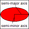
The semi-minor axis is the distance from the hot spot center to its perimeter at its narrowest point, or one-half the minor axis, as shown in the illustration above. For a circle, the semi-major axis is equal to the semi-major axis. The semi-minor axis is never greater than the semi-major axis.
The shape of the hot spot is the ratio of the semi-minor axis to the semi-major axis. The shape will never be greater than 1, and has a lower-limit of 0.2. When the shape is changed, the semi-minor axis is adjusted so that it has the correct ratio with the semi-major axis. The area of the hot spot is also adjusted.
When the hot spot is elliptical, an option is available to fix the angle of the hot spot major axis in relation to the transects by clicking on Degrees and entering the angle in degrees. This may be used when information is available about the angle of the hot spot semi-major axis at the site. It is recommended that the Random option be used unless very reliable information is known about this angle. If the angle is known with near certainty, then entering the angle will result in a transect design with a reduction in the number of transects needed to traverse the hot spot or reduce some of the uncertainty in the estimate of the probability of detection.
Two design objectives are available and are explained below. Parameters shown directly below the Design Objective dropdown are explained within the details of each design objective below.
This design objective focuses only on the probability that at least one transect will traverse the hot spot. When selected, the next parameter on the screen is Required Probability of Traversing Hot Spot, for which the required probability of having one or more transects traverse the hot spot is entered. The required space between transects is returned (printed in red text in the dialogue) based on this input and the defined transect width and hot spot in the Survey Pattern tab.
This parameter is only available when the Design Objective is set to Ensure high probability of traversal only (see the explanation of this Design Objective above). A percentage is entered and the required space between transects is printed below in red text.
The purpose of this option is to make available some of VSP's useful features, such as overlaying transect locations on a site map and exporting transect coordinates to a text or .SHP file. Before deciding to develop a sampling plan based on a user-supplied transect spacing and starting location, consider the assumptions and limitations involved, as detailed in this help file.
The user enters the spacing between transects for the transect design.
Two options are available for starting location: entering X-Y coordinates or using a random start. When X-Y coordinates are selected and entered, it is assumed a transect will pass through those points. Otherwise, random start will assume the transect locations or starting point is random.
Hassig, NL, RF O, JE Wilson, BA Pulsipher, RO Gilbert, CA McKinstry, DK Carlson, and DJ Bates. September 2002. Visual Sample Plan Version 2.0 User Guide, PNNL-14002, Pacific Northwest National Laboratory, Richland, WA.
Hassig N. L., J. E. Wilson, R. O. Gilbert, B. A. Pulsipher, and L. L. Nuffer. 2005. Visual Sample Plan Version 4.0 User's Guide. PNNL-15247, Pacific Northwest National Laboratory, Richland, WA.
Hathaway, J, B. A. Pulsipher, J. E. Wilson, C. A. McKinstry. 2006. Final Report for Statistical Methods and Tools for UXO Site Characterization on Final Simulated Site. PNNL- 15651, Pacific Northwest National Laboratory, Richland, WA.
Gilbert, R. O, J. E. Wilson, R. F. O, D. K. Carlson, B. A. Pulsipher, and D. J. Bates. 2003. Version 2.0 Visual Sample Plan (VSP): UXO Module Code Description and Verification. PNNL-14267, Pacific Northwest National Laboratory, Richland, WA.
Matzke BD, JE Wilson, and BA Pulsipher. 2006. Version 4.4 Visual Sample Plan (VSP): New UXO Module Target Detection Methods. PNNL-15843, Pacific Northwest National Laboratory, Richland, WA.