VSP has a complete room supporting infrastructure, including sampling locations in 3 dimensions and a local coordinate system. Under this system, a room in VSP is any Sample Area that has a height greater than zero. The floor, walls and ceiling can be viewed in the Room View. Objects like doors and windows can be placed in a room. Additional flat surfaces, called surface overlays, can also be placed in the room to represent portions of a surface that need to be distinguished from the overall surface.Surface overlays can also be elevated to represent the top surface of furniture. Samples can be placed on the walls, ceiling, and surface overlays of a room as well as on the floor and on doors and windows. Samples are placed on all selected rooms. To display the Room View, select View > Room from the main menu or click on the Room View tool button on the main toolbar. Many of the VSP room features are described in Section 2.5.1 Drawing a Room.
Some of the menu commands discussed in this chapter also have tool button shortcuts available on the Room Toolbar. To activate the Room Toolbar, select View > Room Toolbar on the main menu.
For help during this section, please refer to the VSP Help Topic Room Menu Commands.
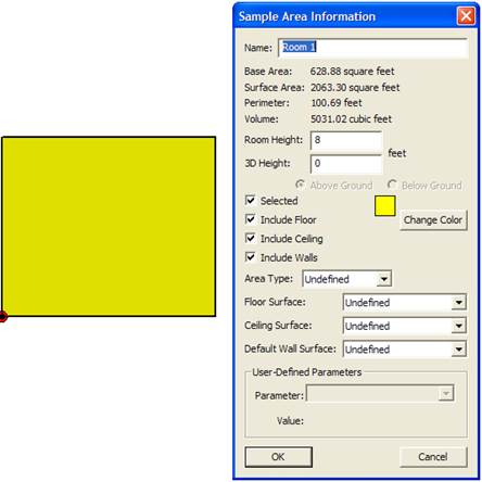
Since a room in VSP is simply a sample area that has had its height set greater than zero, the simplest way to create a room is to create a sample area and set its height to something like 8 feet. To set the height of a room, right-click on the sample area on the map to display the Sample Area Information dialog box (see Figure 6.1). The room height is one of the parameters that can be modified in this information dialog box. The Room > Set Room Height menu command (or Set Height tool button) displays a dialog that sets the height of all selected sample areas when the Map View is active, or sets the height of only the current room when the Room View is active. (See Section 6.2.1 for a definition of current room.)
The Sample Area Information dialog also allows you to include or exclude the floor and the ceiling from a room. These are included by default. If these surfaces are excluded they will not receive sample points from any sampling design and they will not be displayed in the Room view.
Figure 6.1 Sample Area Information Dialog
For help during this section, please refer to the VSP Help Topic Draw Room.
The Room > Draw menu command (or the Draw Room tool button) allows you to draw a room on the map. Drawing a room is similar to drawing a rectangle, except that it automatically sets the wall height for you. Define one corner of the floor rectangle by clicking on the map with the left mouse button or by entering the coordinates on the keyboard (e.g., 100,200). Then enter the opposite corner with the mouse or keyboard. Holding the Ctrl key while clicking on the map limits the floor rectangle to a square.
An alternate method of defining a room is to enter the length, width, and height on the keyboard (Length x Width x Height ). If the room is defined this way, then one corner is placed at the origin (0,0).
If you have a building floor-plan map (such as a .dxf file from a CAD system), the Room Delineation method is usually the fastest and easiest way to create rooms in VSP. Choosing Room > Delineate Rooms from the menu (or clicking the Delineate Rooms tool button) toggles the room delineation mode on or off. The room delineation mode allows you to create rooms with right angles inside existing map shapes. This mode is for use in the map view. If a room contains some walls that are not at right angles to other walls, those rooms will need to be created by the first method outlined in section 6.1.1.
While in this mode, left-clicking with the mouse creates a red rectangle. The red rectangle is framed by moving up, down, left and right from the point clicked and stopping at the first line encountered in that direction. Several red rectangles may be needed to fill up the space inside an irregular shaped room on the map.
After the room is filled with adjoining red rectangles, right-click with the mouse to combine all the rectangles into a room. If there are disjoint red rectangles, each group of red rectangles becomes a separate room. Figure 6.2a and 6.2b illustrates the delineation method in action.
If the desired room is a simple rectangle, right-click with the mouse to create the rectangle and convert it to a room in a single step. Remember the red and black bulls-eye in the bottom left-hand corner of the room in Figure 6.2b marks the location of the Room Origin for local coordinates (see Section 6.4.2).
The room can be modified in the map view by inserting a point into a wall and then moving the wall section. To insert a new point into a wall, use the Map > Insert Point menu command. To move a wall section, select the wall section by holding down the Shift key while clicking on the center of a wall segment. Once selected, the wall segment can be dragged with the mouse. Hold the Ctrl key down while dragging to the wall aligned at right angles. Figure 6.3 illustrates a new point inserted on the right side of a room, the segment selected, and the segment being dragged outward.
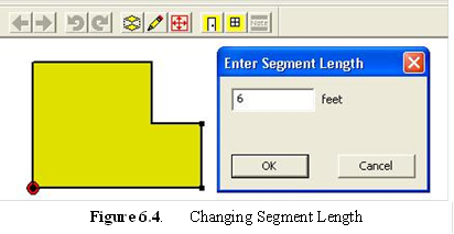
You can also set the exact length of a selected wall segment by right-clicking on it. This displays a dialog that allows you to change the length of the segment. Figure 6.4 illustrates a segment length being changed with the dialog.
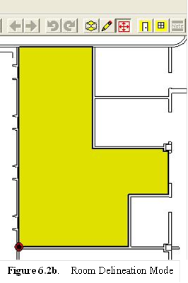
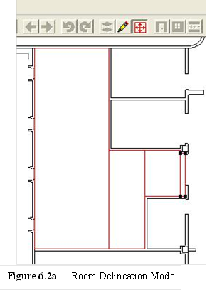
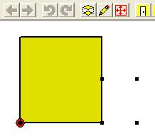
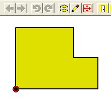
Figure 6.3. Room Manipulation
The Online Help functions provide more detailed instructions on room manipulation.
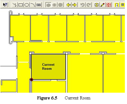
When one or more rooms are selected on a map, exactly one of the rooms is the current room. The current room is the one that is displayed in the Room View. The current room is also indicated on the map by a thick black border and a darker shade. The last room to be created, selected, or viewed with the Sample Information dialog becomes the current room. Using the Room > Next Room or Room > Previous Room menu commands scrolls through the list of selected rooms. Each of these commands also has a tool button. Figure 6.5 shows the current room in the Map View. Remember that samples are placed on all selected sample areas/rooms, not just the current room. If you want to place objects within a room, such as a door or a window, they can only be placed on the current room.
VSP provides 3 different room view types: perspective, wall-strip and splayed. These view types can be selected using the menu commands:
Room > Perspective Room (or Perspective Room tool button)
Room > Room with Wall Strip (or Wall Strip Room tool button)
Room > Splayed Room (or Splayed Room tool button)
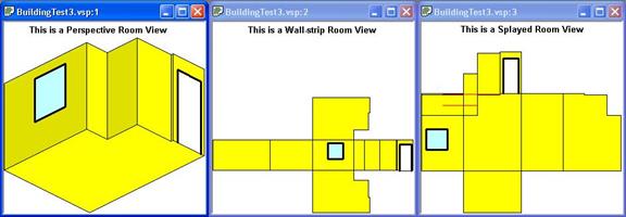
Figure 6.6. Room View Types
The perspective room view shows the room as a 3-dimension semi-perspective view. Inside wall surfaces that are facing you are displayed; inside wall surfaces that are facing away are not displayed. The floor is shown tilted down and the ceiling (if included) is shown tilted up. The wall sections are shown attached to the floor surface. (If the floor is excluded and the ceiling is included, then the wall sections are shown attached to the ceiling surface.)
The Room > Rotate Room Left and Room > Rotate Room Right menu commands (or the Rotate Left and Rotate Right tool buttons) rotate the room by 90 degrees, to allow viewing from a different perspective. This does not change the coordinates of the room or any object associated with the room, such as sample locations.
The wall strip room view shows a floor (if included), a mirror-image ceiling (if included), and a strip of wall sections laid edge to edge. The floor and ceiling surfaces are shown attached to the proper wall section.
The Room > Rotate Room Left and Room > Rotate Room Right menu commands (or the Rotate Left and Rotate Right tool buttons) rotate the room by 90 degrees, to allow viewing the floor and ceiling from different angles. This does not change the coordinates of the room or any object associated with the room, such as sample locations.
The splayed room view shows a floor, a mirror-image ceiling, and individual wall sections laid outward from the floor. The wall sections are originally laid down so that they do not overlap. If the wall section is not shown attached to the floor, a red line shows where it should be attached.
To move a wall section to a new location on the display, simply click and drag with the mouse. Right-click with the mouse on a wall section to move it back to its attached location. Moving a wall section on the display does not change the coordinates of the room or any object associated with the room, such as sample locations.
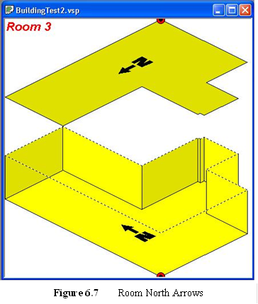
By default, VSP places a north arrow on the room floor and ceiling surface. Figure 6.7 shows the north arrows on the floor and ceiling. Use the View > Room North Arrow command to show or hide the north arrow. The location of the north arrow can be changed by grabbing the center of the north arrow with the mouse and dragging it. (The center to grab is between the N and the arrow.)
VSP assumes by default that north is the top of your map. If this is not the case, select the Map > Map Settings menu command. Change the North Offset in the Map Extents dialog box to correct the direction of north on your map.
 6.2.4 Perspective
Ceiling
6.2.4 Perspective
CeilingIf you prefer not to see the ceiling in the perspective view, use the View > Room Perspective Ceiling command to hide the ceiling.
Doors, Windows, Annotations, and Surface Overlays can be inserted into a room. Figure 6.8 shows a room with a door, window, and annotation.
To insert a door object into the current room, use the Room > Insert Door menu command (or Insert Door tool button). This command can be used in the Map View or the Room View.
After selecting this command, click on one edge of the door and then
on the other edge of the door. On the Map View, the coordinates can also
be entered on the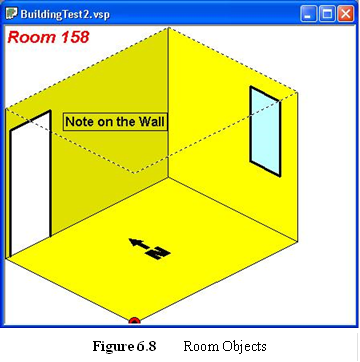 keyboard. Hold the shift key
while clicking to attach the door to the nearest point on the map. Both
edges of the window must be on the same wall section. Note that doors
are inserted into the current room (see section 6.2.1).
keyboard. Hold the shift key
while clicking to attach the door to the nearest point on the map. Both
edges of the window must be on the same wall section. Note that doors
are inserted into the current room (see section 6.2.1).
Doors can be moved, resized or deleted by using the Object Information dialog which is accessed by right clicking on the door. This dialog also allows you to change the door sub-type: Open Door (sample locations will be excluded from the door surface) or Fixed Door (sample locations can be included on the door surface). Figure 6.9 shows the Object Information dialog for a door.
To insert a window object into the current room, use the Room > Insert Window menu command (or Insert Window tool button). This command can be used in the Map View or the Room View.
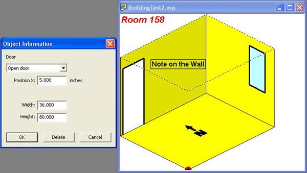
Figure 6.9. Object Information Dialog Box
To use the command in the Map View, click on one edge of the window and then on the other edge of the window. The window will be placed and sized with default heights. The edge coordinates can also be entered on the keyboard. Hold the shift key while clicking to attach the window to the nearest point on the map. Both edges of the window must be on the same wall section. Note that doors and windows are inserted into the current room (see section 6.2.1).
To use this command in the Room View, click on one corner of the window and then on the opposite corner of the window.
Windows can be moved, resized or deleted by using the Room Object Information dialog which is access by right clicking on the window. This dialog also allows you to change the door sub-type: Open Window (sample locations will be excluded from the window surface) or Fixed Window (sample locations will be included on the window surface).
To insert a note object into the current room, use the Room > Insert Annotation menu command (or Insert Note tool button). This command can be used only in the Room View.
Click on the location where you want to place a note. The text, font, color and other attributes can be modified from the Annotation Object Dialog box which is access by right clicking on the note. Notes can be moved by selecting them (by clicking on them) and then dragging them with the mouse.
One or more surface overlays can be inserted in a room to represent a portion of a surface that needs to be distinguished from the overall surface. For example, a portion of the floor in a room may be covered with tile while most of the floor is covered with carpet, requiring a different sampling technique. A surface overlay can be elevated from the floor to represent the top horizontal surface of a desk, chair, cabinet, or shelf. Surface overlays can be placed on any surface in the room. Only floor overlays can be elevated.
To insert a surface overlay into the current room, use the Edit > Surfaces > Create Surface Overlay menu command to bring up the surface overlay dialog box (Figure 6.10). This command can be used only in the Room View (preferably the Perspective Room View). When initially placing a surface overlay, this dialog box is simplified and the only option available is to choose a surface type. Choose the Surface Type from the drop down menu (to add a new surface type, go to Edit > Surfaces > Surface Types). Then click two opposite corners on the room's floor. This will create a rectangular shaped box on the room's floor. Once a surface overlay is placed on a surface, right clicking on it brings up the more extensive dialog box in Figure 6.10. Change this to an elevated surface changing the Height Above Floor (and the sample placement parameters). An example of an elevated surface overlay is in Figure 6.11. Checking the "Allow samples on surface" box will allow sampling on the elevated surface when sampling in the room. Checking "Allow samples on floor beneath surface" allows for sampling to occur underneath the elevated surface. Similarly, checking "Allow samples on wall behind surface" allows for sampling to occur on a section of a wall that a surface overlay is placed against.
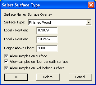
Figure 6.10 Surface Overlay Dialog
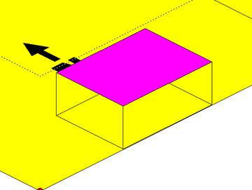
Figure 6.11 Surface Overlay
Edit > Surfaces > Set Surface Types for Selected Rooms presents a dialog that allows you to change the Surface Type for all selected rooms (in the Map view) or the current room (in the Room view). Floor, Ceiling, or Wall surfaces can be changed to one of the defined Surface Types.
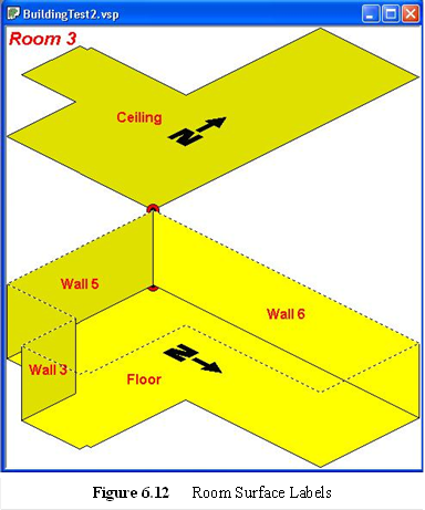
To automatically create a label (annotation or note object) on each surface of a room, use the Room > Label Surfaces command. This command creates a label for each surface in the current room when used in the Room View, or for all selected rooms when used in the Map View. The default labels are:
Floor
Ceiling
Wall 1
Wall 2
Wall ...
This command allows you to choose the Font Type, Size, Style and Color as well as other attributes associated with labels. Figure 6.12 shows room surface labels.
After being created, the surface labels may be edited by right-clicking on them. If this command is run again, it will delete any existing label surfaces and replace them with the default surface labels. The surface label is also reported on the Sample Information dialog (accessed by right-clicking on a sample location). Figure 6.13 shows a Sample Information dialog with a custom surface label.
VSP uses local coordinates to facilitate the location of samples inside of rooms (and also regular sample areas). Local (LX, LY) are relative coordinates. Local coordinates can be viewed on the Sample Information dialog in Figure 6.11.
In regular Sample Areas, the local coordinates are relative to the minimum X and minimum Y coordinates of the sample area.
In Rooms, the local coordinates are relative to the surface they are on. For walls, the local coordinates are relative to the lower left hand corner of the wall section as you are facing it. For the floor and ceiling, the local coordinates are relative to the Room Origin. The location of Room Origin is shown on the Room View by a red and black bull's-eye.
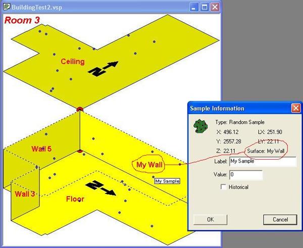
Figure 6.13. Room Surface Labels
By default the Room Origin is the minimum X and minimum Y, but can be changed with the Room > Set Room Origin menu command. Select the new location for the Room Origin by clicking on the Map. Hold down the Shift key while clicking to attach the Room Origin to an existing point on the map. The Room Origin can also be set by entering the coordinates on the keyboard.
VSP provides a fixed room label at the upper left corner of each Room View. Although this label cannot be hidden, the font, color and other label attributes can be modified by left clicking on the label. The same color and styles are used for each Room View.